Geosystems have manufactured point load testers (PLT’s) in Australia for several years. During this time we have advised customers on how best to utlise PLT’s in the geotechnical sector. As a result, we thought it was high time to publish a “point load testers explained” article answering customer’s frequent questions.
What is a point load tester?
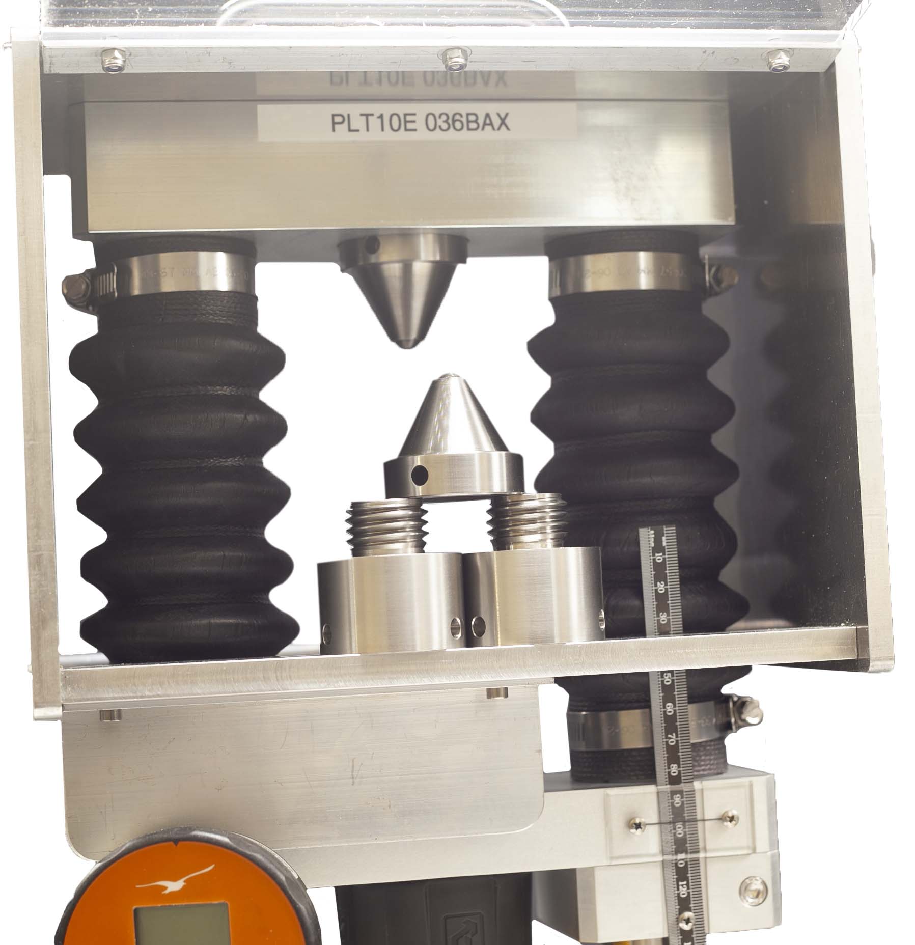
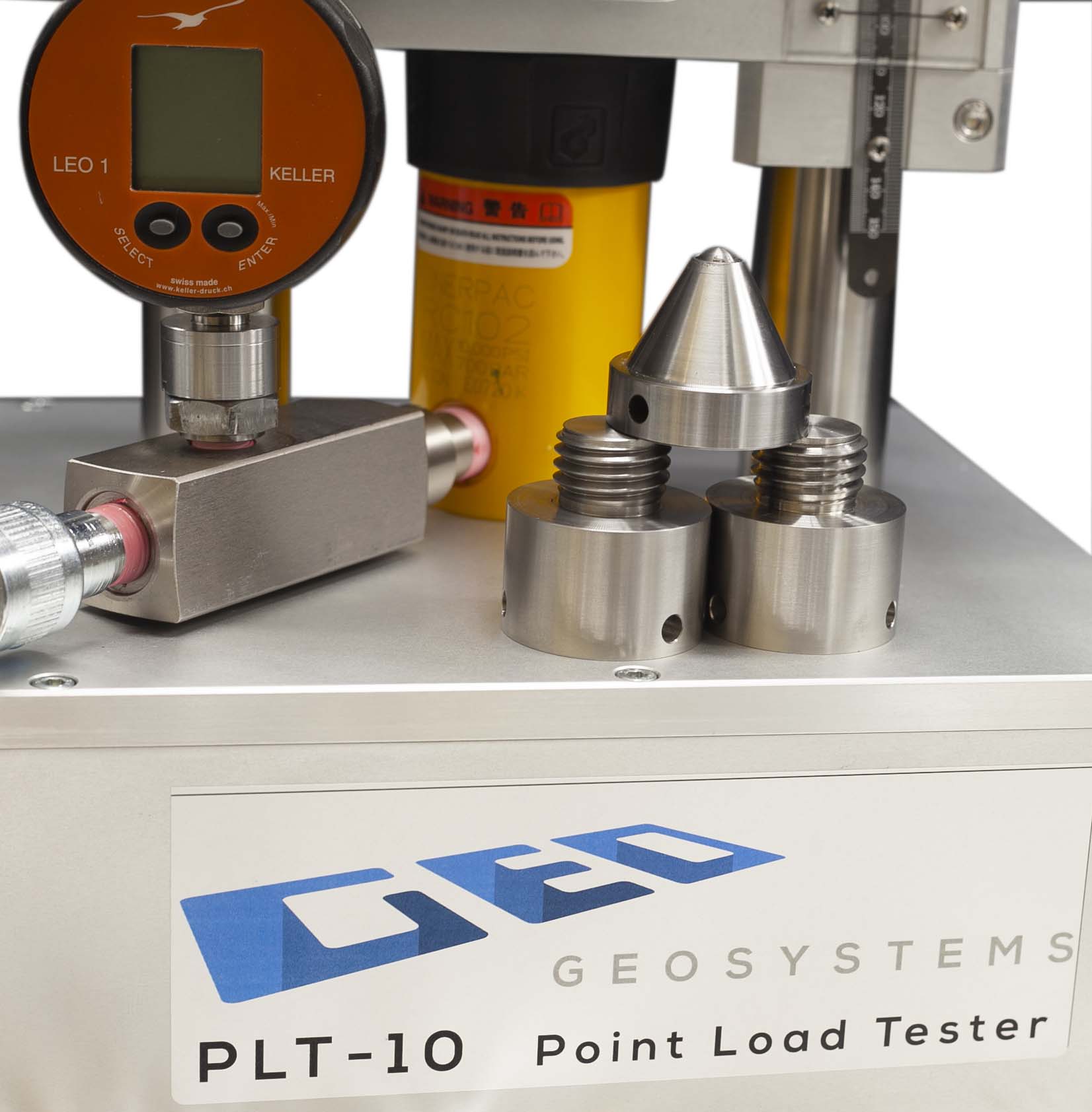
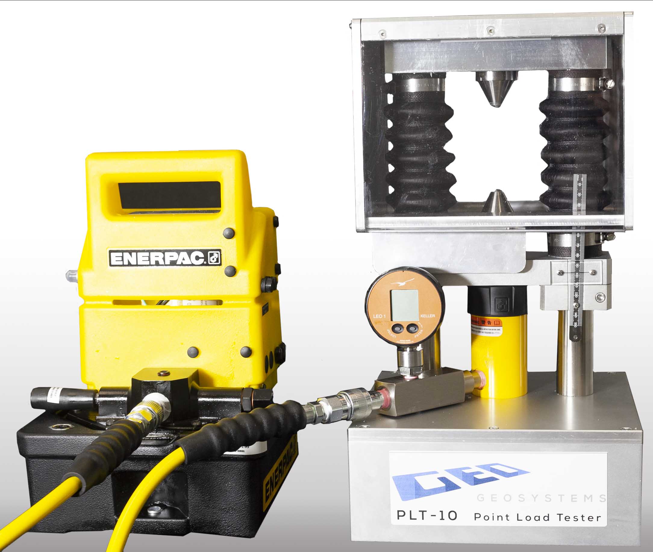
A point load tester is a simple press to test for rock strength.
During the core sample test, the gauge records the maximum point load (in kN). The strength index obtained can be correlated with the uniaxial compressive strength (kN) of the rock tested.
Point load tester deployment.
By design, point load testers are compact and portable. As such, rock sample testing alongside the drilling rig is possible. Consequently, accurate in-situ results can be obtained immediately and while the sample is still ‘fresh’. Without the in-situ testing, samples would need shipping to a rock test facility in a core sample box. A process that could take days to yield results. A point load test allows the user to easily delineate zones of rock of different strength properties in minutes not days.
Point load tester uses.
Point load testers become most useful in large-scale mining and civil engineering projects for classifying rock types. Primarily for rock classification and characterisation.
Understanding the rock classifications and characterisation allows mining operations improve the design, increase mine milling efficiency, and ultimately money savings.
This is different from other rock test applications where rock strength makes up one of the five parameters for rock mass classification, critical for tunnelling engineers to make decisions on tunnelling support, tunnel maximum span, appropriate rock bolt patterns and use of mesh. The five basic characterisation parameters are
- Strength of intact rock material (measured by PLT)
- Rock Quality Designation RQD
- Spacing of joints
- Condition of joints
- Groundwater conditions
Fluctuations in ore hardness and feed size distribution at mines can have a significant influence on crusher and mill performance. In some operations, significant problems with mill stability occur when feed size is not well controlled . The manipulation of the ROM feed size creates opportunities to improve crushing and milling equipment performance and efficiency. Mine to Mill optimisation is a great tool for managing the variabilities in hardness and fragmentation.
Mine to Mill.
Mine to Mill methodology utilises simple and inexpensive ore characterisation measurements that can be performed by trained site personnel. Consequently, quite often the operation already collects the measurements. The advantage of simple measurements is the amount of data that can be collected in a very short timeframe, as the limited number of samples require shipping to an outside laboratory. When attempting to characterise an entire orebody, the density of data is very important.
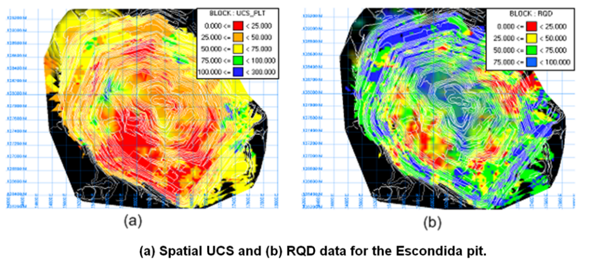
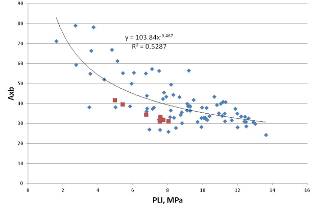
For ore characterisation, we use measurements of rock strength (Point Load Index, PLI and/or UCS) and rock structure (Rock Quality Designation, RQD and/or fracture frequency). Both PLI (see Figure 1) and RQD measurements (Figure 2) can be taken on drill core and Point Load tests can also be performed on core (full/half) and/or irregularly shaped samples of material. The PLI value can be correlated to Uniaxial Compressive Strength (UCS) as well as the JKMRC Drop Weight test parameters A and b (Figure 3).
Drop weight parameters
The Drop Weight parameters are necessary in order to model the crushing and grinding circuits. Therefore, the use of the Point Load Index allows sites to characterise their rock properties quickly and easily while still making use of the sophisticated grinding models that are available. Ordinarily, it is enough to collect 15-30 samples for SMC testing (for getting Axb parameters) and correlate the results to PLI. Before sending samples to SMC testing, the mine site should test the samples for PLI.
The RQD value represents the rock structure, this indicates the fracture frequency present in the drill core. Consequently, the RQD value is routinely taken at operations for geotechnical purposes. However, the RQD proves very useful in blast fragmentation modelling in the absence of detailed rock mass structure mapping. We also use the window mapping data collected by site personnel, scanline mapping data and/or digital photogrammetric techniques (if available).
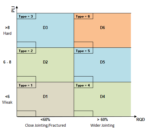
Rock property mapping
Mapping the range of rock properties and defining blast domains (Figure 4) is possible once the PLI and RQD (or fracture frequency) data are available. Within each domain, the material will behave similarly in the blasting, crushing and grinding processes while all of the domains cover the complete range of rock properties that are present. We use this data for blast fragmentation simulations to determine the size distributions of the ROM feed (Figure 5).